How do I calibrate the XY offset with Ultimaker Cura
If you want to set the XY offset very precisely, you need a different tool than Weedo offers. For our setting you need a vernier caliper or a micrometer. If possible, use two identical materials from the same manufacturer, but different colors, for the setting. First of all, the dimensional accuracy must be checked and adjusted. This is important so that you can use different materials and manufacturers together (materials have different shrinkage, etc.) Perform the dimensional calibration e.g. according to the instructions Teaching Tech 3D Printer Calibration. The correction factors are inserted in the Cura Configuration X40 PRO. You may not need to do this then. Then print the 2x2 checkerboard pattern without an offset (middle of the settings on the touch display). If the offset is greater than 2mm, then the tension on the belt is no longer correct. If necessary, adjust the belt or the offset.
Cura Plugin
Firmware
With the Weedo X40 1.2.5 firmware and the X40 PRO firmware up to version 1.2.5.6, X is then nominal size 353mm. From X40 PRO firmware 1.2.5.7 the nominal size is 5mm smaller (347mm) due to the bug fix. For the latest X40 PRO firmware, a correspondingly adapted gcode is therefore also required, which you can only generate via the latest X40 community Ultimaker Cura configurations for the Weedo X40 PRO or have to adapt the slicer accordingly.
For a conversion from a 1.2.5.6 version to a newer X40 PRO version you only have to reduce the X value by 5mm (e.g. via the M218 command or the backup function). From firmware version 1.2.5.9 you can specify the XY offset with an accuracy of two decimal places.
- Weedo X40 Stock Firmware 1.2.5 => 353mm +2.5mm / -2.4mm
- Weedo X40 PRO Firmware up to 1.2.5.6 => 353mm +2.5mm / -2.4mm
- Weedo X40 PRO Firmware 1.2.5.7 and 1.2.5.8 => 347mm +2.5mm / -2.4mm
- Weedo X40 PRO Firmware 1.2.5.9 or newer => 347mm +2.55mm / -2.44mm
Please note that the firmware stores the offset via the offset GUI's internal button numbers. When changing the firmware, problems can therefore arise due to the different offset values. The easiest way is to set the offset using the M218 command. After that, the GUI works as usual.
M218 Command
You can not only enter the XY-Offset via the printer display, but also transfer it to the printer via the M218 command. The firmware can only store offset values that can also be entered on the printer via the display. If you send values outside the valid range to the printer via the M218 command, then the value is changed to the allowed min or max value. After you have sent the new value to the printer via M218, the value must be stored in the EEPROM via the M500 command.
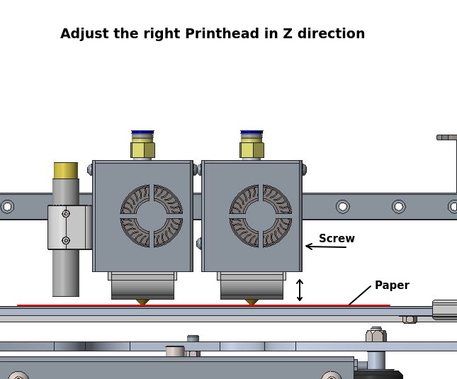
Z-Offset Calibration
Some have trouble getting the Z-Offset on the Weedo X40 print head right, so here's my tip. If your print bed is not aligned, then perform a manual bed leveling beforehand. Start the printer and move both printheads to the center of the print bed. Use the arrow keys on the display to move the printheads about 0.5 to 1mm over the print bed. Use a sheet of paper and place it between the print bed and both nozzles. Loosen the screw from the right extruder to adjust the height. Carefully lower the print heads using the arrows on the display until the sheet is pinched at the left nozzle. Press the right nozzle against the sheet of paper while tightening the screw. Both nozzles should now be pinching the paper and aligned. If the right nozzle is longer than the left one, you must first lower the left nozzle using the screw. Finally, don't forget to start the Z offset via the display.
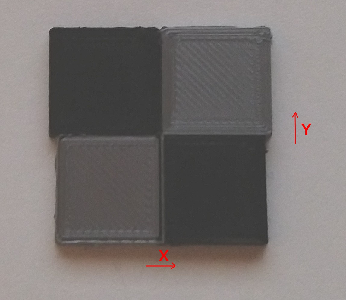
XY-Offset Calibration with 2x2 Checkerboard
In the x40 community cloud directory there is a subdirectory with the name XYZ_Calibration_Tool.
- Download the files XYZ_calibration_2x2_part1.stl and XYZ_calibration_2x2_part2.stl.
- Create the print model with Cura according to the instructions.
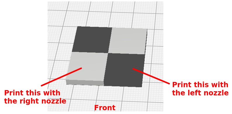
- Print the model with two different colors and without an offset (Average dimension for the touch display, X=353). The left front rectangle should be printed with the left nozzle and the right front rectangle with the right nozzle so that it is easier to see whether the offset needs to be increased or decreased. It is recommended to use AddNorth E-PLA, as the material has very low shrinkage and can reproduce the edges very nicely. Before releasing the model from the platform, check the offset and note the orientation of the model to the axes. You can also write the orientation of the model with a pen.
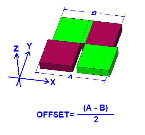
- Now measure the rectangle with a caliper. The rectangle should measure 30mm x 30mm. If it is smaller or larger, then you very likely have an offset.
If there is a deviation of 1,5mm or more, the belt should be retightened. The X offset is limited to 353 +/-2.5 (347+/-2.5 up X40 PRO Firmware version 1.2.5.7) by the firmware. Larger or smaller values are not accepted!
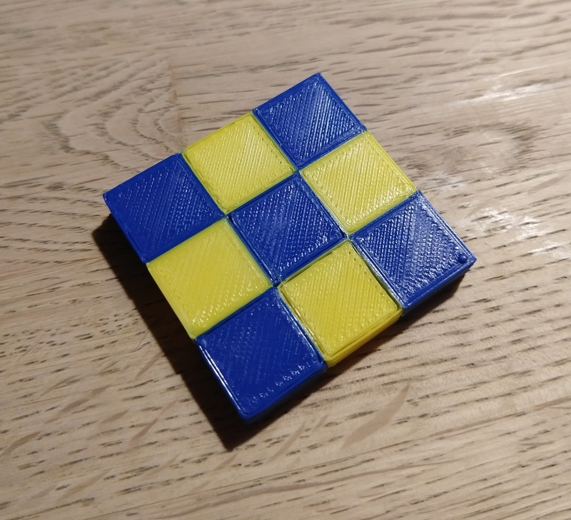
If the dimension of the front row is smaller than that of the rear, then the dimension of the offset must be increased. If the dimension is larger, the offset must be reduced. In my example, the rectangle measures 31mm or 29mm in the X direction and 30mm in the Y direction. So we have an positv offset of 1mm in the X direction.
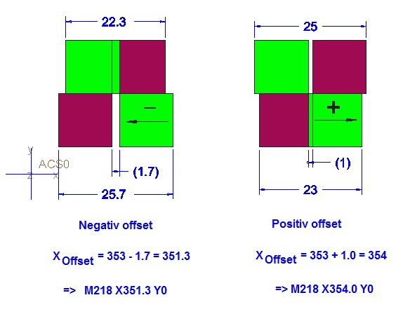
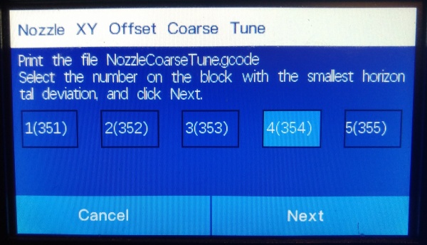
To correct the offset, I go to the XY-Offset menu on the printer and shorten the distance by 1mm. I switched from 5 (353) to 4 (352). Depending on the firmware version, the dimensions of the picture may be different. Weedo integrated corrections in the course of the software development.
To be on the safe side, I'll print the model again to check the change. If the surface of the checkerboard pattern is not to form a continuous plane, then the nozzle must also be set in the Z direction.
You can also transmit the offset via Pronterface or Octoprint with the M218 command. Enter e.g. M218 T1 X354.0 to set the offset to 354.0mm. Alternatively, a parameter backup can also be performed on the MicroSD card. Then simply open the config.sav file with a text editor and adapt the M218 accordingly. After saving, reinsert the MicroSD card into the printer and import it again using the parameter function.
Superfine tuning
With the X40 PRO firmware version 1.2.5.9, SuperFine Tuning is introduced. The XY offset can then be set with an accuracy of 0.01mm.
Before printing from the chessboard, please check whether the target line width matches the actual line width. If not, then the line width must be adjusted via the material flow.
The offset is set perfectly when the outer dimensions (within the scope of printing accuracy) are the same everywhere.
If the fields on the chessboard are not to be connected sufficiently, then the material flow should be increased slightly. The outer dimensions and the overlap will then be slightly larger.
How do I recognize a properly tuned XY-Offset?
With the best possible matched XYZ offset, in the 2x2 checkerboard pattern, the outer dimensions A and B are identical in the X and Y directions and all four rectangles are fully connected to one another at the connecting surfaces. In addition, the surface (Z-direction) forms a continuous surface without a clearly noticeable offset between the colors. The colors must also form a clean separation and not be clearly visibly printed into one another.