
Tuning
X40 PRO Extruder upgrade
The Weedo 40 extruder is one of the weak points of the device. Actually, you don't want to spend money on a new extruder right away after you buy it, but at some point the extruder drive pinion will lock up or you want to process very stiff filament and that doesn't work because the material transport doesn't work properly.
I would therefore like to introduce you to an upgrade option here. The BMG extruder was originally developed by Bondtech and is also available in similar versions from other manufacturers.
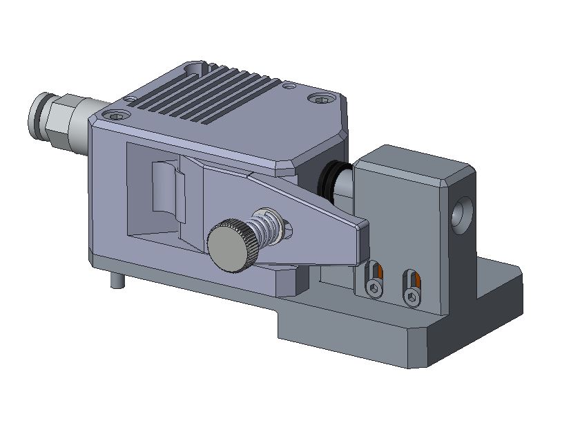
The BMG extruder has a gear ratio and two drive gears between which the filament is clamped. Due to this design, the extruder can generate high thrust forces very precisely. It is hardly possible for the filament to slip through. In addition, the extruder is made entirely of metal and is also available as a left/right version. Ideal conditions for a durable Idex printer upgrade.
BMG advantages:
- Extremely high feed force
- LH/RH variant fixes the small bending radius of PTFE tubing on the left Weedo extruder
- The extruder enables printing with smaller nozzles with a diameter of 0.2mm
- Due to the gear ratio, the filament is extruded evenly even at slow printing speeds. The printed image should therefore be improved at slow and very high printing speeds.
- Durable as it is made entirely of metal and has ball bearings
Due to the slightly higher overall height of the extruder, the height of the installation space is somewhat reduced. If you want to avoid a collision with very high parts, you should reduce the build volume height in Cura. The slightly higher design has no effect on the synchronization of the Z-axes in the bed leveling function. The synchronization just takes a little longer.
For the upgrade I used the Fysetc BMG extruder. The left and right variant together can be found on AliExpress for less than 50EUR.
Shopping links see Weedo X40 Wear parts, spare parts and tuning parts
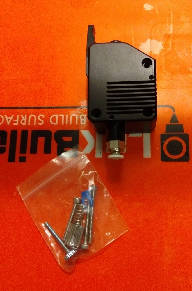
Fysetc BMG RH Extruder
However, an adapted firmware is required for use with the Weedo X40, since the direction of rotation has to be reversed with the right extruder. The X40 PRO BMG variant can therefore be downloaded from the X40 community cloud.
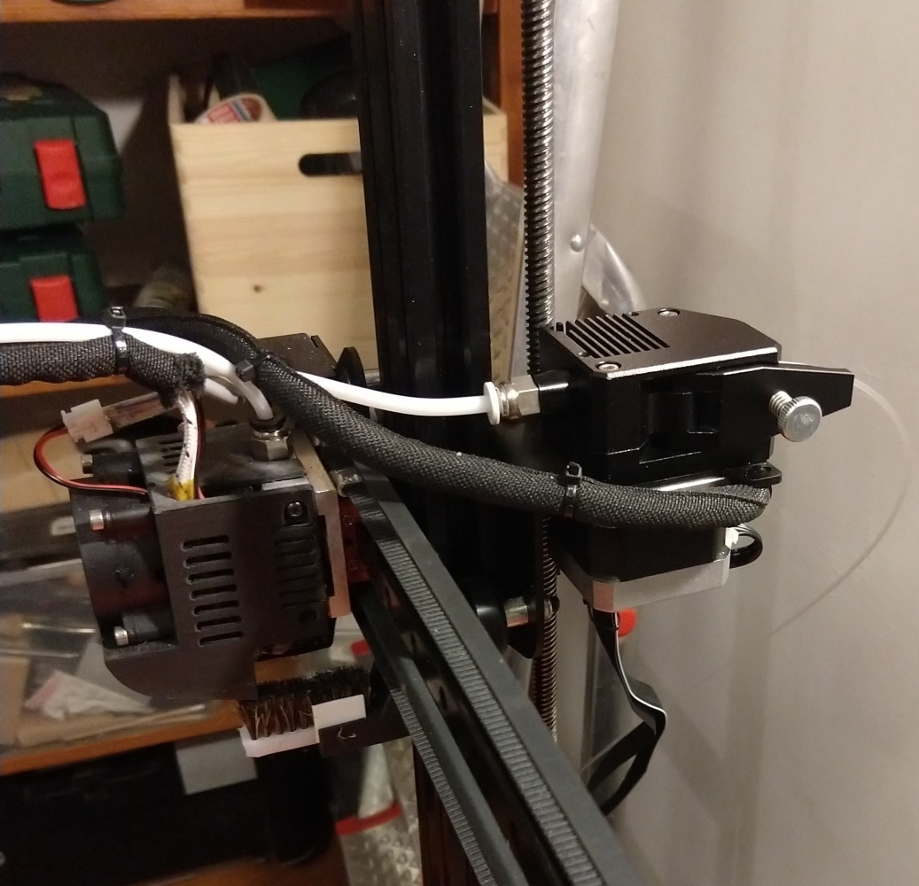
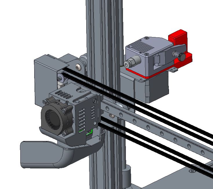
Installed Fysetc BMG LH Extruder
Installation and setup from the extruder
After installing the BMG extruder, you must update the firmware to the X40 PRO BMG variant, because the direction of rotation must be reversed for the right extruder. The X40 BMG PRO variant already contains the calibration of my Fysetc all metal BMG extruders.
Extruder and axis calibration
Please note:
If you want to use the X40 community print profiles without an adjustment, then you have to calibrate the printer with the reference material AddNorth E-PLA. All other print profiles, if necessary, are an offset to the E-PLA.
Even if you use the same extruder and the parameters are stored in the firmware, you must carry out an extruder and axis calibration for dimensionally accurate parts, since the manufacturing tolerances of the extruder and also the belt tension affect the result.
- Reset the calibration parameters to an integer value. To do this, connect the computer to Pronterface or OctoPrint via USB and send it the following control command:
M92 X94 Y94 Z400 E390(for Fysetc BMG Extruder)M500 - Remove the Bowden cable on the extruder, add the extruder filament with the most exact 1.75mm diameter possible. Cut off the protruding end directly at the extruder. Heat the nozzle to around 200°C and extrude 100mm of filament. Cut off the protruding piece of filament on the extruder and measure the length. You can easily calculate the new E-Steps on the TechingTech homepage. Save the new E-Steps using the M92 command and repeat the process to check the filament length.
M92 E388.64M500 - Print a rectangle with a line thickness of 0.4mm and a layer height of 0.2mm as described under Teaching Tech Slicer Flow Calibration. Calculate the new flow parameters and transfer the new flow values to the printer with the M221 command. You can't save the M221 value with the M500 command. Please add the M221 command with the new value to the Cura startcode. The material flow from the M221 command is not overridden by Cura, but the M221 flow and the Cura flow values are multiplied. After you have corrected the flow using the M221 command, you should repeat the print test with the AddNorth E-PLA at 100% material flow and a line width of 0.4mm. If you have done everything correctly, the wall thickness of the print object should now also be 0.4mm.
If you don't want to use the M221 command, then you need to adjust the Cura Flow value of all printing profiles. The printing result is identical!
Please remember to reinsert the parameter when updating Cura!M221 S89(add the M221 command in the Cura startcode to adapt the printer to the X40 community printing profiles) - Now the axes have to be calibrated. To do this, do a bedleveling and z-offset beforehand so that the printer has the best possible basis. Follow the How to calibrate the Weedo X40 printer. Print out the XZY calibration cube with AddNorth E-PLA (Flow 100%) and check the dimension.
- To verify the calibration, print the XYZ cube this time with a scale of 200%, resulting in a cube with an edge length of 40mm. The finished cube should deviate from the nominal size by a maximum of 0.1 mm in the XY direction. If the discrepancy is larger, you did something wrong or didn't work accurately enough.
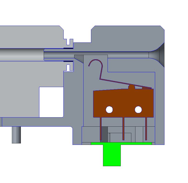
Runout Sensor
The runout sensor also doesn't work for many. The defect is often not recognized because the test program does not check the sensor.
Download:
Useful hints
A clogged nozzle can cause filament to accumulate in the extruder, leading to further errors. Since the filament accumulates in the extruder housing, the problem cannot be seen from the outside. If the nozzle is clogged, the extruder should therefore also be dismantled and taken apart.
- Details
- Hits: 23143
PID-Tuning
In order to get good print results, the nozzle and print bed temperature must remain as constant as possible.
The firmware has integrated a control loop for this purpose.
PID stands for proportional, integral and differential. In contrast to a one-point or two-point controller, it is a so-called continuous controller. The variable to be controlled is the control deviation, i.e. the deviation between the target and actual states at a specific point in time.
In order for the PID to work properly, the firmware must be informed of the PID parameters. The firmware has an automatic function to determine the PID parameters.
We have determined the PID parameters for you and integrated them into the Cura start code. You don't really need to do anything that the printers of the Weedo X40 Kickstarter Edition should all be identical.
To compensate for any deviations, you could determine the parameters as follows.
As already described in Article How to calibrate the extruder, we use Prontaface again to send control commands to the printer.
Report default Firmware Settings
M503
Switch on the left hotend fan
M106 E0 S255
Auto-tune hotend at 210 °C for 8 cycles:
M303 E0 C8 S210
After the process has been completed, make a note of the Kp, Ki and Kp parameters.
Auto-tune bed at 60 °C for 8 cycles:
M303 E-1 C8 S60
- Details
- Hits: 6557
Filament collection container
- Original Weedo Filamentbox (gcode)
- Weedo X40 Filament Bucket
- Weedo X40 Purge Bucket
- Upgraded Weedo X40 Mounted Purge Bucket
Wipe brush bracket
Fan Duct
- Weedo X40 MODDED FAN DUCT (tested, brings no improvement. The X40 community cooling system should be used here)
- Details
- Hits: 2692
Here are some tips, tricks and workarounds from users. If you have any questions, please contact the author.
Super Slow Z Movement Workaround:
Author: baZzz
On the X40 PRO firmware version 1.2.0.3, the default feed rate for the Z-axis has been increased to 120
Fix Hot-end\Heatsink\Heat-break\Heat-creep Update:
Author: Warren Flack (Flackenstein)
If you experience z-height nozzle changes in either the left or right extruder it could be because of the small grub screw (M2 x 2mm set screw) stripping or not grabbing the heat break. The heat sink milling for the heat-break throat has too much air space around it and because of that there isn’t sufficient heat transfer to the heat sink and this can cause filament to melt high up in the heat tube. Fixing requires a bit of mechanical intervention and the following steps enhance heat break retention and reduce heat-creep.
Tools to complete the task:
x40 allen wrenches, (#29, #30, #31 or 2.9mm, 3.1mm, 3.3mm) drill bits, 4mm tap, tap/drill oil
Parts:
4mm 0.7pitch by 6mm set screw, High Temp thermal paste (Slice Engineering Boron Nitride Paste, Protronix Series 9 Thermal Paste)
- Remove the hot-end module from the linear rail block.
- Remove set screw from the right side of the heat sink and remove the nozzle assembly.
- Detach the heat-sink from the hot-end assembly
- Step drill the heatsink set screw hole using #29, #30, and #31 drill bits. You can also use 2.9mm, 3.1mm, and 3.3mm drill bit sizes. Recommend applying a drop of tap/drill oil for a clean drill.
- Tap the drill hole for a 4mm 0.7 pitch screw. For a good tap use a drop of the tap oil again
- When done, clean and degrease the heatsink.
- Apply a small drop of the thermal compound to the set screw threads and insert into the heat block. Insert the set screw just enough to not block the heat break / throat insertion.
- Apply a conservative amount of thermal compound to the heat break throat and insert into the heatsink
- Tighten the set screw – with the 4mm by 6mm long set screw you will get a significantly more secure connection to the heat break and in combination with the thermal paste better heat reduction.
- Clean up any excess thermal paste and inspect the tube for any thermal paste that may have entered during install.
View the image from the Weedo X40 webcam through a browser:
You can display the images from the Weedo X40 camera on a browser without a special app. The printer only has to be registered in your network and you have to know the IP address of the printer or assign a name to the printer in the router.
Camera settings:
- http://IP-address:8080/
To stream the live video, enter the following in the browser:
- http://IP-address:8080/?action=stream
To take a webcam photo, enter the following in the browser:
- http://IP-adress:8080/capture
With, the printer has the IP address 192.168.178.41 and the name Weedo-X40. So it is also possible:
- http://192.168.178.41:8080/?action=stream
- http://Weedo-X40:8080/?action=stream
Please note that only one device can access the webcam at a time. For example, if you take a time-lapse recording using Octoprint, you cannot watch the live stream on your smartphone at the same time. The same applies to the live stream and photo function. The photo function cannot be used during a live stream.
Set the Z-Level and Bed Level correctly
The correct setting of the Z-height is particularly important with the X40, since an incorrect Z-setting can damage the printer. The Weedo X40 is equipped with a so-called proximity switch. This sensor switches when a magnetic material reaches a distance of approx. 4mm. Since the printer cannot keep exactly at a distance of 0mm between the nozzle and the bed when taking measured values, a safety distance must be provided.
Printer setup
- Use the handwheels on the bed to adjust the corners of the bed so that the compressed spring is approx. 10mm long. If the distance is too great, it can happen that the bed set changes or becomes possible in XY movements. If the spring length is too short, the bed cannot be raised because the spring is on the stand.
- Use the arrow keys to move the left nozzle to the center of the print bed. Finally, use the arrow buttons on the display to reduce the distance between the nozzle and the heating bed to approx. 1-1.5mm. Now loosen the screws from the sensor and adjust the sensor so that the LED on the sensor just lights up.
- Now reduce the distance between the nozzle and the bed to approx. 0.5 mm. Carefully approach the corners of the bed, making sure that the nozzle does not collide with the bed. Now roughly adjust the bed using the handwheels so that there is approx. 0.5mm air between the nozzle and the bed.
- Now perform Z-Offset on the display. After the platform has been measured, the nozzle moves to the center of the bed. Place a sheet of paper between the nozzle and the bed and use the arrow keys to reduce the distance until the ball can just barely move. The offset value displayed should now be between -1mm and -1.5mm. If the offset is between -1mm and 0mm or even in the positive range, then the switching point of the sensor is wrong and a crash can occur. If necessary, adjust the sensor again. The sensor should switch when the nozzle is about 1mm to 1.5mm away from the bed. Click Save and complete the process and save the offset value!
- Now carry out bed leveling via the display and set the bed exactly. The Z-height and the bed should now be set correctly. If the nozzle touches the print bed when using the bed knife, then you have done something wrong. When measuring, the nozzle must not touch the bed and certainly not press it down, otherwise the printer will spin and the printer may be damaged!
Feed the filament into the extruder
If you compress the spring using the lever and try to insert the filament, it very often gets stuck. You can solve the problem by starting the insertion of the filament on the display and only when the extruder wheel is turning, insert the filament without actuating the lever. After the process is complete, pull back the lever and advance the filament to the nozzle. Then start the insertion on the display again.
It's that easy!
Hotend glued with plastic
The component has detached itself from the platform and the hotend is completely glued with plastic. How do I get the hotend clean again?
Heat the hotend and use a tool to clean the hotend as well as possible. Dismantle the nozzle, the heating block and the heat break. Place the nozzle, the heating block without insulation, heating cartridge and temperature sensor, as well as the Hearbrake in a glass with acetone. Seal the jar and wait a few days. Acetone dissolves most plastics. In between, remove heavy soiling with the scraper. Reinstall the cleaned hotend. A drawing of the hotend with the individual parts can be found on the X40 Community Cloud.
If you also have a tip or found a workaround, send it to database (at) x40-community.org for publication
- Details
- Hits: 135641
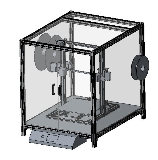
Weedo X40 printer casing with heating in progress ...
Specifications:
- Control unit in front of the printer housing
- Robust housing
- Compliance with fire protection guidelines (plastic parts UL 94 V-0)
- Housing that is as gas-tight as possible with filter system or exhaust air
- Housing heating for printing ABS and ASA
- Housing should reduce vibrations and noises
- Easy access to the printer for e.g. filament changes or partial removal
- Drawers to catch the filament
- Filament rolls on the side or in the printer with easy access
- Details
- Hits: 5252