How to calibrate the Weedo X40 printer
As a beginner, many of you ask why do I actually have to calibrate a printer and what is behind it?
In order to get a perfect print result, various parameters such as printing temperature, printing speed, line width, etc. must be perfectly coordinated. This is the only way to get a component that has good looks, stability and dimensional accuracy. So it all ties together.
If you calibrate the Weedo X40 PRO and use the latest Cura configuration for the Weedo X40 PRO, you will get very good print results using the adjusted and tested print profiles without having to set any parameters. The components are as dimensionally accurate as possible (corrected material flow and shrinkage compensation are included in the printing profiles).
Example:
The print table or print head moves at speed X, but the extruder motor has too high a speed and transports the filament too fast. So too much material / time is pressed out of the nozzle. A so-called overextrusion occurs. The line width becomes too thick, the print object is not nice and not true to size.
Preparation
We assume that you want to adapt the Weedo X40 printer to the X40 community Cura print profiles so that the print profiles work perfectly.
The AddNorth E-PLA filament was used as reference material for the Cura printing profiles. The material has only a small diameter tolerance and shrinkage. Therefore, it is perfectly suited to avoid calibration errors caused by deviations from the 1.75 mm filament diameter and shrinkage.
A 20mm cube printed with the Weedo X40 and AddNorth E-PLA (100% material flow and 100% shrinkage compensation) should have a maximum deviation of +/-0.05mm with perfect coordination. If you do not use the Weedo X40 with the original extruder, it may be that the material foot has to be adjusted to the Cura printing profiles with the M221 command!
For the best possible calibration, you should get the following:
- A roll of AddNorth E-PLA (250g is enough, color of your choice. I used yellow)
- An outside micrometer with digital display and three decimal places (measuring range 0-25mm)
To perform the calibration, you need software that can send gcode commands to the printer via the USB port. If you want to use a PC, you can use the free Pronterface software. You can also do this with a Raspberry Pi and OctoPrint (you can find a ready-to-use image in the X40 Community Cloud).
Install PC Software
- Install the CH340 driver on your Windows PC
- Install the Pronterface Software on your Windows PC
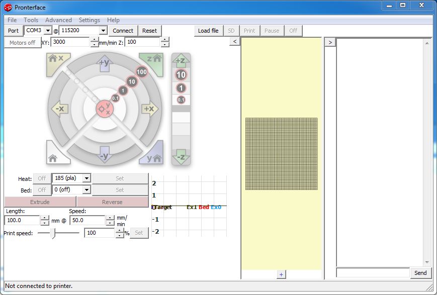
Connect the printer to the PC using the supplied USB cable. Set the baud rate for Pronterface to 115200. Try out port COM1, COM2, etc. To do this, click on Connect, wait a few seconds and then click on Reset. The Weedo X40 is a bit tricky, when establishing the connection, if it does not work immediately, try several times.
Tipp:
If you do not have a PC running Pronterface and have the latest X40 PRO firmware installed on the printer, then you can also calibrate using the printer and the MicroSD card. You can use the display to view the parameters, use the arrow keys to perform the movements and you can adjust the M92 parameters by backing up the parameters to the MicroSD card, opening the text file on the SD card and adding the M92 commands. You then only have to restore the backup and the M92 parameters have also been changed and also saved in the EEPROM.
Printer calibration
Please note that the order of calibration is important. Therefore, work through the steps in the specified order, otherwise you will not get the right results!
Since the extruders on the left and right of the Weedo X40 are identical in construction or are mirror images of the BMG Upgarde, you only need to calibrate one extruder. A different calibration of the left and right extruder is not enabled in the firmware.
1. Extruder Steps
When calibrating the extruder, a kind of digital gear ratio is adjusted so that with a gcode command to extrude 100mm material, 100mm material is actually transported.
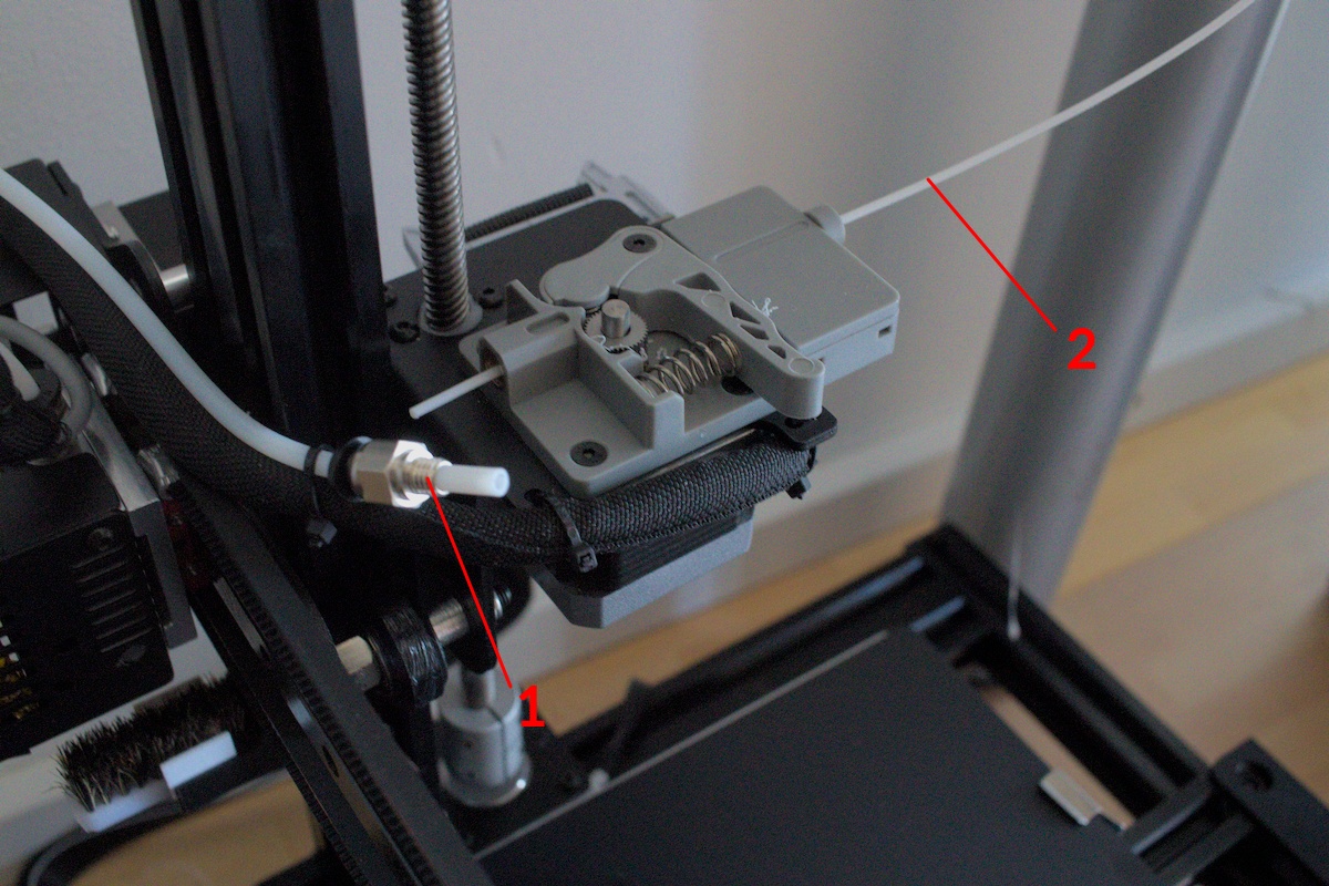
After the connection from the PC to the printer works, remove the filament from the extruder. Disconnect the Bowden cable from the extruder and insert the filament into the extruder until it sticks out a little.
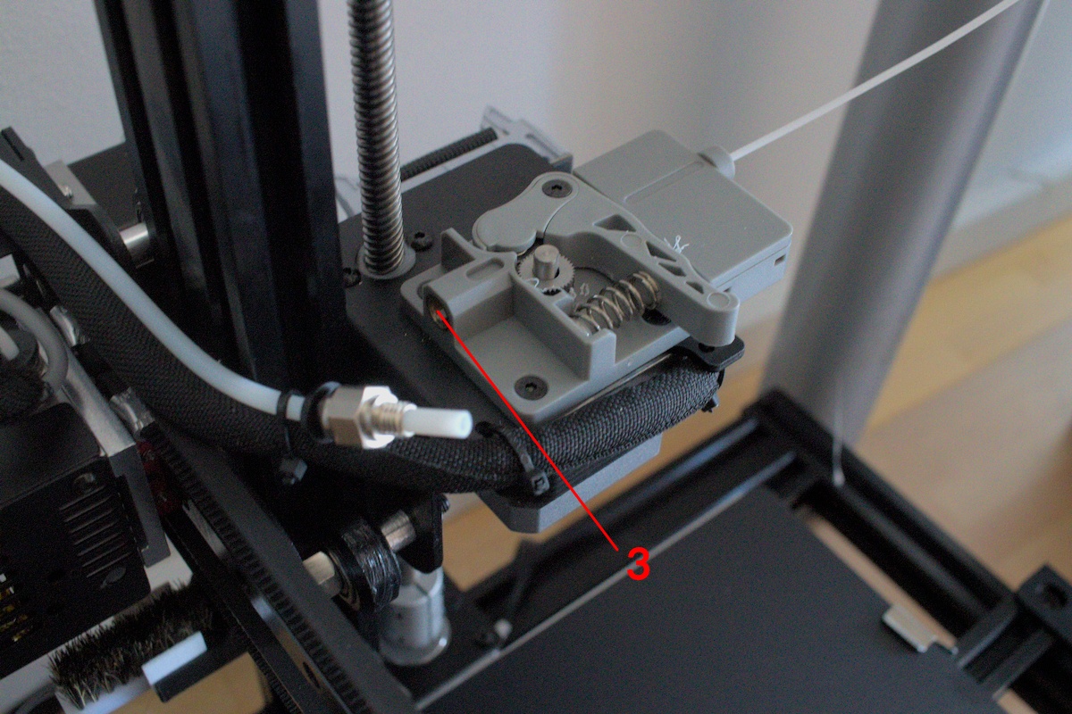
Now cut the filament with the supplied pliers directly at the extruder exit. The filament should now be flush with the extruder (3).
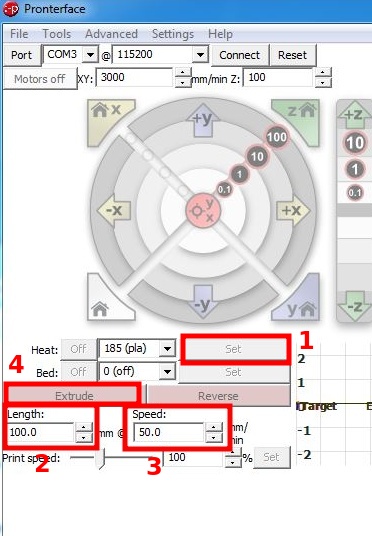
Now heat the nozzle via Pronterface. Enter 100.0 for Lenght and 50.0 for Speed.
Click on Extrude to execute.
After the extruder has conveyed the material, cut it off directly at the extruder exit as before. To measure the length of the extruded piece of filament. The best way to do this is to press the filament against a ruler.
Establish the connection to the PC with Pronterface and execute the M92 command. Note the current XYZ and E-value from the steper motors. With the X40 PRO firmware, you can also view the current parameters on the display.
We calculate the new E-value as follows:
NEW E-value = (100 / Measured Filament length) * Current E-Value
You can specify the new extruder calibration values in Cura's startup code like we did earlier or save them to EEPROM.
To save the new extruder calibration, run the following commands with Pronterface:
M92 E<NEW E-VALUE>
M500
To check, I recommend extruding and measuring 100mm filament again as described above. If the length deviates more than 1mm, then the process should be repeated.
You can use the M92 or M503 command to check whether the printer has accepted the new values.
You only have to carry out the process on one extruder, since the firmware only accepts one value for both extruders. The tool specification T0 or T1 is not necessary.
2. Axis calibration
The calibration of the axes is one of the most important points in order to be able to print dimensionally accurate components. During axis calibration, the target travel path is compared with the actual travel path of the print head or print bed and corrected if necessary. Unfortunately, the calibration is often done incorrectly, since components are simply printed, measured and the parameters are determined. Since every plastic has more or less shrinkage (including PLA), this creates an faulte.
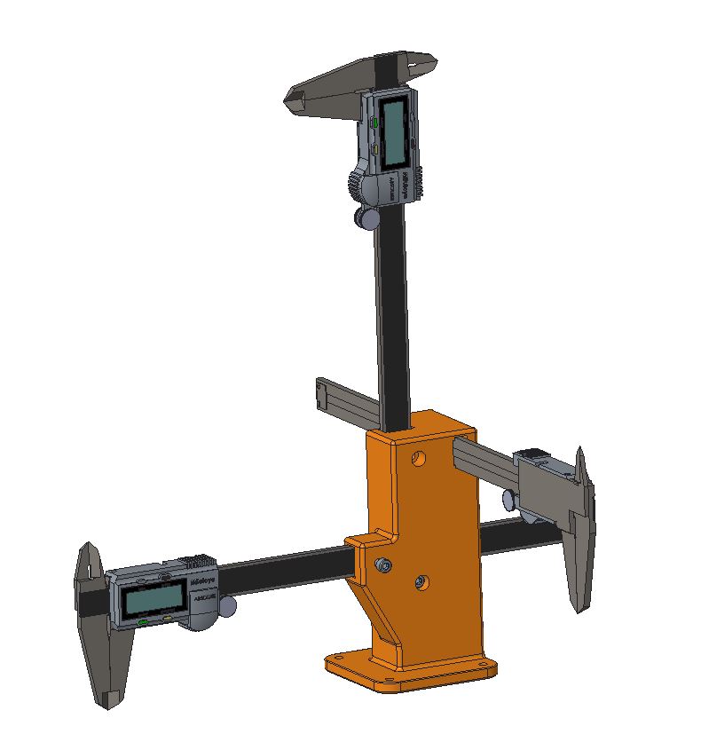
The correct way is to measure the movement of the print head or print bed with a dial indicator or caliper. If you opt for a high-precision dial gauge, you should also buy a dial gauge holder with a magnetic base. I would therefore like to show you how to do it correctly with a 15EUR caliper.
You need a digital caliper with a display accuracy of two decimal places (0.01 mm) for the implementation.
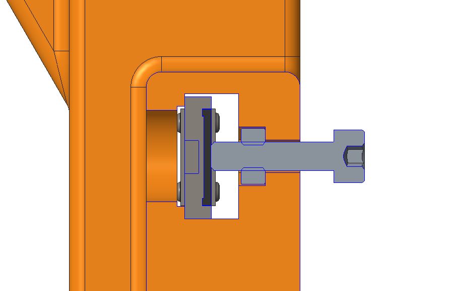
To attach the caliper, all you have to do is print the tool, e.g. from PLA (do not remove it from the platform), attach the caliper with an M4 nut and screw. After measuring in the XYZ direction, you can then remove the tool from the platform. An adapter plate is planned with which the tool can be reused, hence the four holes in the base plate.
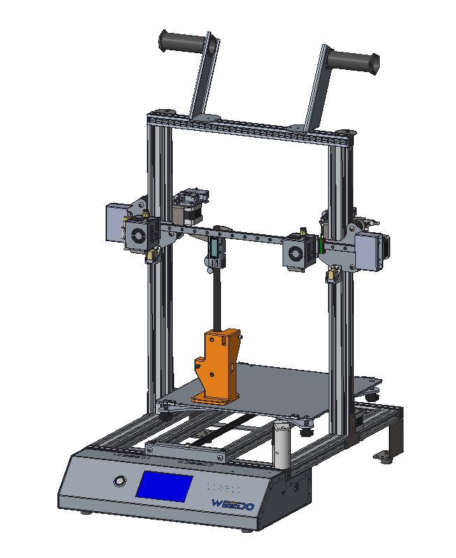
In order for the measurements to be carried out, the calibration tool must be printed in the front left corner of the platform.
 |
|
You can move the print head or print bed using the arrow keys on the display or via Pronterface. Measure the travel of 10mm per axis several times and determine the average value per axis. Measuring the Z-axis is difficult because the print bed is spring-loaded and the Weedo X40 also has a Z-accuracy problem. Several test prints and corrections are recommended here to achieve a good value.
We calculate the new XYZ-value as follows:
NEW XYZ-value = (Travel Distance / Measured Travel Distance) * Current XYZ-Value
Example for X-Axis:
X Travel Distance = 10.00mm
X Measured Travel Distance = 9.90mm
Current X-Value (Reported by M92 or M503): 80.5
=> <NEW X-VALUE> = 81.31
To save the new extruder calibration, run the following commands with Pronterface:
M92 X<NEW X-VALUE> Y<NEW Y-VALUE> Z<NEW Z-VALUE>
M500
For more information see https://teachingtechyt.github.io/calibration.html#xyzsteps
3. PID Tuning (PID = Proportional–Integral–Derivative)
With an FDM printer, the desired line temperature is produced via a heating cartridge, a temperature sensor and a control circuit. A control requires control parameters that influence the adjustment and maintenance of the cell temperature. With poor control parameters, the cell temperature is significantly exceeded at peaks, after which it falls well below the cell temperature and then approaches the cell temperature in smaller waves. If the parameters are bad, this takes a correspondingly long time and can thus disrupt the safety monitoring of the firmware and trigger a corresponding "Heating Failed Error".
The Marlin firmware contains a routine for determining the control parameters. Since the Weedo X40 has identical hardware installed on the left and right side of the nozzle, you only have to determine the parameters with one nozzle. The identical parameters are used for the other side. If you carry out the process several times, you will notice that the parameters are always slightly different. The parameters do not have to be as precise as with axis calibration. You may also not notice any change afterwards because the old parameters were good enough.
Reconnect the printer to your PC to send control commands via Pronterface/Octoprint. We assume that the test is performed with the left nozzle.
Turn on the left nozzle fan with the following command:
M106 T0 S255
| If you plan to print mostly PLA, PID tuning at 200°C should give you good results. If you want print at a wide range between 200 and 280°C, than run PID tining at 240°C. |
Run the PID autotune with the following command:How to use the X40-Community print profiles
M303 E0 C8 S240 U1
Now we save the new parameters and switch the fan off again:
M500
 M106 T0 S0
If you do not want to save the new parameters in the EEPROM, you can also store them in the Cura start code. For more information see https://teachingtechyt.github.io/calibration.html#pid
The Weedo X40 print bed does not have a corresponding control, so the PID autotuning can only be carried out with the nozzle heating.
After calibration, you may have to adjust your material parameters such as material flow and shrinkage compensation.
For more information see Cura shrinkage compensation and Set the XYZ offset
Printer calibration also affects correct XY offset. You should at least check the XY offset, e.g. by printing a chessboard pattern and correct it if necessary. For more information see Set the XYZ offset.
On the X40 PRO firmware version 1.2.5.6, all important parameters can be saved on the microSD card with the parameter backup function and, of course, restored if lost.
Happy printing